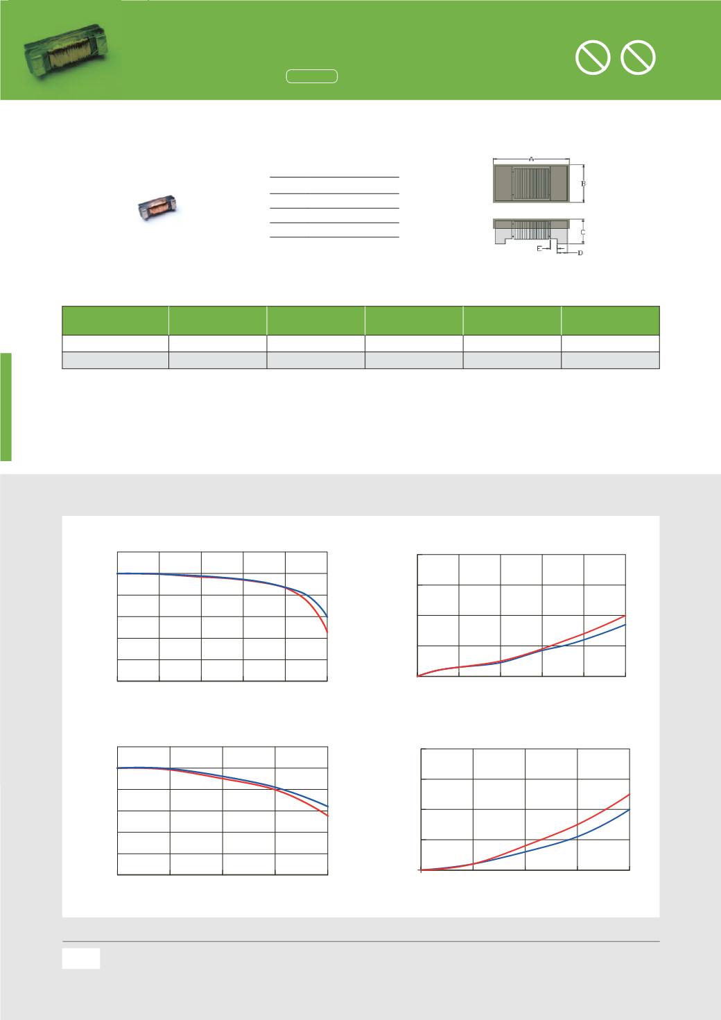
DC Bias Characteristics (Typical)
All the data listed in this catalogue are for reference only, TAI-TECH reserves the right to alter or revise the specificatio
notification.
For the latest specification, please visit our website:
Specifications
A
11.50
±
0.30
B
3.50
±
0.30
C
2.50
±
0.30
D
1.50
ref.
Units: mm
DC Bias Characteristics (Typical)
0 0.02 0.04 0.06 0.08 0.1
DC Current(A)
0
20
40
60
80
100
120
L(%)
PAS1225F-252M
30
s delay
0
s delay
0
0.02 0.04 0.06 0.08 0.1
DC Current(A)
0
10
20
30
40
TEMP. RISE(
o
C)
PAS1225F-252M
30
s delay
0
s delay
0
0.01
0.02
0.03
0.04
DC Current(A)
0
20
40
60
80
100
120
L(%)
PAS1225F-133M
30
s delay
0
s delay
0
0.01
0.02
0.03
0.04
DC Current(A)
0
10
20
30
40
TEMP. RISE(
o
C)
PAS1225F-133M
30
s delay
0
s delay
Part Number
Inductance
(
uH)
±20%
Test Frequency
(
Hz)
I rms
(
mA) max.
DC Resistance
(
Ω) ±10%
SR
(
KHz)
PAS1225F-252M
2500
0.1
V/125K
60
18
50
PAS1225F-133M
13000
0.1
V/1K
30
87
22
Note:
1.
All test data referenced to 25
℃
ambient.
2.
Testing Instrument : L/Q: Agilent-4192A, Agilent-16334A ; Irms:CH3302,CH1320 ; SRF: Agilent-4291B ; Rdc: Agilent-34420A
3.
Rated Current (Irms) will cause the coil temperature rise approximately
Δ
t of 20
℃ .
4.
The part temperature (ambient + temp rise) should not exceed 85
℃
under worst case operating conditions.Circuit design,component,PC
thickness,airflow and other cooling provisions all affect the part temperature. Part temperature should be verified in the end application
5.
Special inquiries besides the above common used types can be met on your requirement.
88
PAS 1225 Series
4814
inch
Dimensions
Specifications
Chip Size
Units: mm
A
11.50
±0.30
B
3.50
±0.30
C
2.50
±0.30
D
1.50
ref.
Part Number
Inductance (uH)
±
20%
Test Frequency (Hz)
I rms (mA) max.
DC Resistance (
Ω
)
±
10%
SRF (KHz) min.
PAS1225F- 2M
2500
0.1
V/125K
60
18
500
PAS1225F-133M
13000
0.1
V/1K
30
87
220
Note:
1.
All test data referenced to 25
℃
ambient.
2.
Testing Instrument : L/Q: Agilent-4192A, Agilent-16334A ; Irms:CH3302,CH1320 ; SRF: Agilent-4291B ; Rdc: Agilent-34420A
3.
Rated Current (Irms) will cause the coil temperature rise approximately
Δ
t of 20
℃
.
4.
The part temperature (ambient + temp ris ) should not xceed 85
℃
under worst case operating conditions.Circuit design,component,PCB trace size and
thickness,airflow and other cooling provisions all affect the part temperature. Part temperature should be verified in the end application.
5.
Special inquiries besides the above common used types can be met on your requirement.
Hearing Aid (HAC) Inductors
Halogen
Halogen-free
Pb
Pb-free
All the data listed in this catalogueare for reference only,TAI-TECH reserves the right toalter or revise the specificationswithout prior
notification.
For the latest specification,please visit ourwebsite:www.tai-tech.com.tw
Hearing Aid (HAC) Inductors
(1808
inch)
Dimensions
Specifications
Chip Size
A
4.40
±
0.20
A’
4.75
±
0.20
B
2.00
±
0.20
B’
2.25
±
0.20
C
1.80
±
0 20
C’
1.80
±
0.30
D
0.80
ref.
Units: mm
Part Number
Inductance
(
uH)
±10%
f
L0
(
kHz)
SRF
MHz(min)
DC Resistance
(
Ω) ±10%
Rated Current
(
mA) max.
PAS4420F-252M-F10
2500
10
1
82
40
PAS4420F-352K-F10
3500
10
1
85
20
Note:
1.
Test frequency:Inductor(L):10KHz /0.1V;
2.
All test data referencedto 25
℃
ambient.
3.
Testing Instrument : L/Q:Agilent-4192A,Agilent-16334A ; Irms:CH3302,CH1320 ;SRF:Agilent-4291B ;Rdc:Agilent-34420A
4.
RatedCurrent (Irms)will cause the coil temperature rise approximately
Δ
tof20
℃ .
5.
Thepart temperature (ambient + temp rise) should not exceed85
℃
underworst caseoperating conditions.Circuitdesign,
component,PCB trace size and thickness,airflow and other cooling provisions all affect thepart temperature.Part temperature
should be verified in the endapplication.
6.
Special inquiries besides theabove commonused types can bemeton your requirement.
DC Bias Characteristics (Typical)
0
10
20
30
40
50
60
DCCURRENT(mA)
0
10
20
30
40
50
60
70
80
90
100
110
120
130
140
L(%)
PAS4420F-252M-F10
30
s delay
0
sdelay
0
10
20
30
40
50
60
DCcurrent(mA)
0
10
20
30
40
50
60
TEMP.RISE(
o
C)
PAS4420F-252M-F10
30
s delay
0
s delay
0
0.01
0.02
0.03
0.04
DCCURRENT(A)
0
10
20
30
40
50
60
70
80
90
100
110
L(%)
PAS4420F-352K-F10
30
s delay
0
s delay
0
0.01
0.02
0.03
0.04
DCcurrent(A)
0
5
10
15
20
25
30
TEMP.RISE(
o
C)
PAS4420F-352K-F10
30
s delay
0
sdelay
86
All the data listed in this catalogueare for reference only,TAI-TECH reserves the right toalter or revise the specificationswitho
notification.
For the latest specification,please visit ourwebsite:www.tai-tech.com.tw
Hearing Aid (HAC) Inductors
(2508
inch)
Dimensions
Specifications
Chip Size
A
6.40
±
0.30
B
2.30
±
0.20
C
1.80
±
0.20
D
0.90
ref.
E
0.50
ref.
Units: mm
Part Number
Inductance
(
uH)
±10%
f
L0
(
kHz)
SRF
MHz(min)
DC Resistance
(
Ω) ±10%
Rated Current
(
mA) max.
PAS6420F-701K-F10
700
10
2.45
12
80
Note:
1.
Test frequency : Inductor(L) : 10KHz /0.1V;
2.
All test data referenced to 25
℃
ambient.
3.
Testing Instrument : L/Q: Agilent-4192A,Agilent-16334A ; Irms:CH3302,CH1320 ; SRF: Agilent-4291B ; Rdc:Agilent-34420A
4.
Rated Current (Irms) will cause the coil temperature rise approximately
Δ
t of 20
℃ .
5.
The part temperature (ambient + temp rise) should not exceed 85
℃
under worst case operating conditions.Circuit design,
component, PCB trace size and thickness, airflow and other cooling provisions all affect the part temperature. Part temperature
should be verified in the end application.
6.
Special inquiries besides the above common used types can be met on your requirement.
DC Bias Characteristics (Typical)
0
0.02
0.04
0.06
0.08
0.1
DCCURRENT(A)
0
10
20
30
40
50
60
70
80
90
100
110
L(%)
PAS6420F-701K-F10
30
s delay
0
s delay
0
0.02
0.04
0.06
0.08
0.1
DCcurrent(A)
0
5
10
15
20
25
30
35
40
45
50
TEMP.RISE(
o
C)
PAS6420F-701K-F10
30
sdelay
0
s delay
88
All the data listed in this catalogue are for reference only, TAI-TECH reserves the right to alter or revise the speci cations without prior noti cation.
For the latest speci cation, please visit our website:
Remark


