DC Bias Characteristics (Typical)
All the data listed in this catalogue are for reference only, TAI-TECH reserves the right to alter or revise
Specifications
D
0.90
E
0.50
Units: mm
Part Number
Inductance
(
uH)
±10%
f
L0
(
kHz)
SRF
MHz(min)
DC Resistance
(
Ω) ±10%
PAS6420F-701K-F10
700
10
2.45
12
Note:
1.
Test frequency : Inductor(L) : 10KHz /0.1V;
2.
All test data referenced to 25
℃
ambient.
3.
Testing Instrument : L/Q: Agilent-4192A, Agilent-16334A ; Irms:CH3302,CH1320 ; SRF: Agilent-4291B ; Rdc: Agilent-34420
4.
Rated Current (Irms) will cause the coil temperature rise approximately
Δ
t of 20
℃ .
5.
The part temperature (ambient + temp rise) should not exceed 85
℃
under worst case operating conditions.Circuit design,
component, PCB trace size and thickness, airflow and other cooling provisions all affect the part temperature. Part temperat
should be verified in the end application.
6.
Special inquiries besides the above common used types can be met on your requirement.
DC Bias Characteristics (Typical)
0
0.02
0.04
0.06
0.08
0.1
DC CURRENT(A)
0
10
20
30
40
50
60
70
80
90
100
110
L(%)
PAS6420F-701K-F10
30
s delay
0
s delay
0
0.02
0.04
0.06
0.08
0.1
DCcurrent(A)
0
5
10
15
20
25
30
35
40
45
50
TEMP. RISE(
o
C)
PAS6420F-701K-F10
30
s delay
0
s delay
Specifications
D
0.90
r
E
0.50
r
Units: mm
Part Number
Inductance
(
uH)
±10%
f
L0
(
kHz)
SRF
MHz(min)
DC Resistance
(
Ω) ±10%
PAS6420F-701K-F10
700
10
2.45
12
Note:
1.
Test frequency : Inductor(L) : 10KHz /0.1V;
2.
All test data referenced to 25
℃
ambient.
3.
Testing Instrument : L/Q: Agilent-4192A, Agilent-16334A ; Irms:CH3302,CH1320 ; SRF: Agilent-4291B ; Rdc: Agilent-34420A
4.
Rated Current (Irms) will cause th coil temperature rise approximately
Δ
t of 20
℃ .
5.
The part temperature (ambient + temp rise) should not exceed 85
℃
under worst case operating conditions.Circuit design,
component, PCB trace size and thickness, airflow and other cooling provisions all affect the part temperature. Part temperatur
should be verifi d in the end application.
6.
Special inquiries be id the above common used types can be met on your requirem nt.
DC Bias Char cterist cs (Typical)
0
0.02
0.04
0.06
0.08
0.1
DC CURRENT(A)
0
10
20
30
40
50
60
70
80
90
100
110
L(%)
PAS6420F-701K-F10
30
s delay
0
s delay
0
0.02
0.04
0.06
0.08
0.1
DCcurrent(A)
0
5
10
15
20
25
30
35
40
45
50
TEMP. RISE(
o
C)
PAS6420F-701K-F10
30
s delay
0
s delay
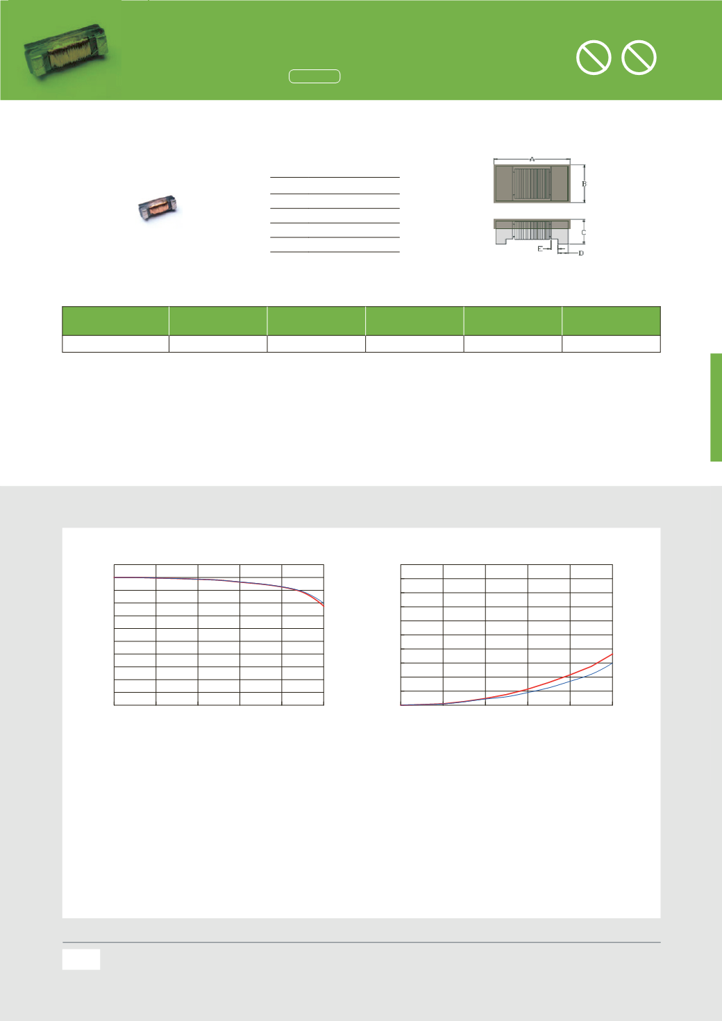
PAS 6420 Series
2508
inch
Dimensions
Specifications
Chip Size
Units: mm
A
6.40
±0.30
B
2.30
±0.20
C
1.80
±0.20
D
0.90
re .
E
0.50
ref.
Part Number
Inductance (uH)
±
10%
f
L0 (kHz)
SRF MHz(min)
DC Resistance (
Ω
)
±
10%
Rated Current (mA)
max.
PAS6420F-701K-F10
700
10
2.45
12
80
Note:
1.
Test frequency : Inductor(L) : 10KHz /0.1V;
2.
All test ata refere ced to 25
℃
ambient.
3.
Testing Instrument : L/Q: Agilent-4192A, Agilent-16334A ; Irms:CH3302,CH1320 ; SRF: Agilent-4291B ; Rdc: Agilent-34420A
4.
Rated Current (Irms) will cause the coil temperature rise approximately
Δ
t of 20
℃
.
5.
The part temperature (ambient + temp rise) should not exceed 85
℃
under worst case operating conditions.Circuit design, component, PCB trace size and
thickness, airflow and other cooling provisions all affect the part temperature. Part temperature should be verified in the end application.
6.
Special inquiries besides the above common used types can be met on your requirement.
Hearing Aid (HAC) Inductors
Halogen
Halogen-free
Pb
Pb-free
All the data listed in this catalogueare for reference only,TAI-TECH reserves the right toalter or revise the specificationswithout prior
notification.
For the latest specification,please visit ourwebsite:www.tai-tech.com.tw
Hearing Aid (HAC) Inductors
(1808
inch)
Dimensions
Specifications
Chip Size
A
4.40
±
0.20
A’
4.75
±
0.20
B
2.00
±
0.20
B’
2.25
±
0.20
C
1.80
±
0 0
C’
1.80
±
0.30
D
0.80
ref.
Units: mm
Part Number
Inductance
(
uH)
±10%
f
L0
(
kHz)
SRF
MHz(min)
DC Resistance
(
Ω) ±10%
Rated Current
(
mA) max.
PAS4420F-252M-F10
2500
10
1
82
40
PAS4420F-352K-F10
3500
10
1
85
20
Note:
1.
Test frequency:Inductor(L):10KHz /0.1V;
2.
All test data referencedto 25
℃
ambient.
3.
Testing Instrument : L/Q:Agilent-4192A,Agilent-16334A ; Irms:CH3302,CH1320 ;SRF:Agilent-4291B ;Rdc:Agilent-34420A
4.
RatedCurrent (Irms)will cause the coil temperature rise approximately
Δ
tof20
℃ .
5.
Thepart temperature (ambient + temp rise) should not exceed85
℃
underworst caseoperating conditions.Circuitdesign,
component,PCB trace size and thickness,airflow and other cooling provisions all affect thepart temperature.Part temperature
should be verified in the endapplication.
6.
Special inquiries besides theabove commonused types can bemeton your requirement.
DC Bias Characteristics (Typical)
0
10
20
30
40
50
60
DCCURRENT(mA)
0
10
20
30
40
50
60
70
80
90
100
110
120
130
140
L(%)
PAS4420F-252M-F10
30
s delay
0
s delay
0
10
20
30
40
50
60
DCcurrent(mA)
0
10
20
30
40
50
60
TEMP.RISE(
o
C)
PAS4420F-252M-F10
30
s delay
0
s delay
0
0.01
0.02
0.03
0.04
DCCURRENT(A)
0
10
20
30
40
50
60
70
80
90
100
110
L(%)
PAS4420F-352K-F10
30
s delay
0
s delay
0
0.01
0.02
0.03
0.04
DCcurrent(A)
0
5
10
15
20
25
30
TEMP.RISE(
o
C)
PAS4420F-352K-F10
30
s delay
0
s delay
86
All the data listed in this catalogueare for reference only,TAI-TECH reserves the right toalter or revise the specificationswitho
notification.
For the latest specification,please visit ourwebsite:www.tai-tech.com.tw
Hearing Aid (HAC) Inductors
(2508
inch)
Dimensions
Specifications
Chip Size
A
6.40
±
0.30
B
2.30
±
0.20
C
1.80
±
0.20
D
0.90
ref.
E
0.50
ref.
Units: mm
Part Number
Inductance
(
uH)
±10%
f
L0
(
kHz)
SRF
MHz(min)
DC Resistance
(
Ω) ±10%
Rated Current
(
mA) max.
PAS6420F-701K-F10
700
10
2.45
12
80
Note:
1.
Test frequency : Inductor(L) : 10KHz /0.1V;
2.
All test data referenced to 25
℃
ambient.
3.
Testing Instrument : L/Q: Agilent-4192A,Agilent-16334A ; Irms:CH3302,CH1320 ; SRF: Agilent-4291B ; Rdc:Agilent-34420A
4.
Rated Current (Irms) will cause the coil temperature rise approximately
Δ
t of 20
℃ .
5.
The part temperature (ambient + temp rise) should not exceed 85
℃
under worst case operating con itions.Circuit design,
component, PCB trace size and thickness, airflow and other cooling provisions all affect the part temperature. Part temperature
should be verified in the end application.
6.
Special inquiries besides the above common used types can be met on your requirement.
DC Bias Characteristi s (Typical)
0
0.02
0.04
0.06
0.08
0.1
DCCURRENT(A)
0
10
20
30
40
50
60
70
80
90
100
110
L(%)
PAS6420F-701K-F10
30
s delay
0
s delay
0
0.02
0.04
0.06
0.08
0.1
DCcurrent(A)
0
5
10
15
20
25
30
35
40
45
50
TEMP.RISE(
o
C)
PAS6420F-701K-F10
30
sdelay
0
s delay
87
All the data listed in this catalogue are for reference only, TAI-TECH reserves the right to alter or revise the speci cations without prior noti cation.
For the latest speci cation, please visit our website:
Remark


