Soldering and Mounting
Soldering
Mildly activated resin fluxes are preferred. TAI-TECH terminations are suitable for all wave and re-flow soldering systems. If hand soldering
cannot be avoided, the preferred technique is the utilization of hot air soldering tools.
1.
Solder Re-flow:
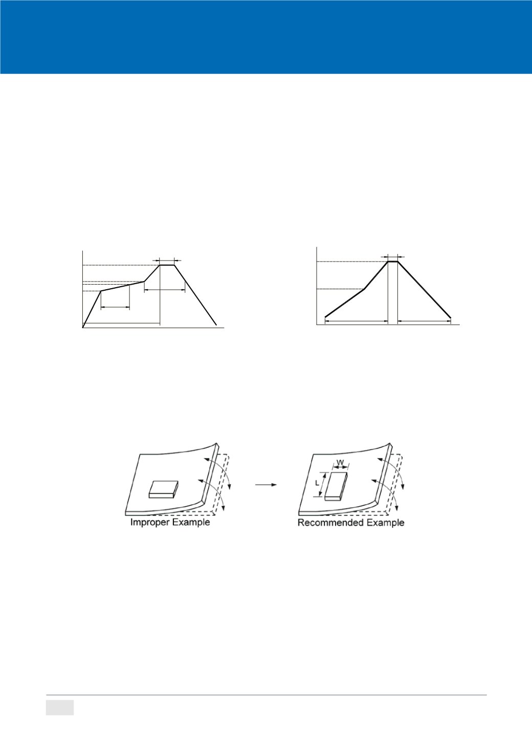
Recommended temperature profiles for re-flow soldering in Figure 1.
2.
Soldering Iron (Figure 2):
Products attachment with a soldering iron is discouraged due to the inherent process control limitations. In the event that a soldering iron
must be employed the following precautions are recommended.
‧
Preheat circuit and products to 150
℃
‧
Never contact the ceramic with the iron tip
‧
Use a 20 watt soldering iron with tip diameter of 1.0mm
‧
355
℃
tip temperature (max)
‧
1.0
mm tip diameter (max)
‧
Limit soldering time to 4~5 sec.
3.
PC BoardWarping:
PC Board is recommended to be signed so that the on-board products are not subjected to the mechanical stress caused by warping the PC
Board. The improper layout or direction might damage the on-board products.
(
As Fiqure 3. shows, products should be located in the sideways direction (Length:L > W) to avoid the mechanical stress.)
Mounting
Please contact TAI-TECH sales representative to require the specific products “Specification for Approval” to obtain the details of Land pattern
dimensions.
All the data listed in this catalogue are for reference only, TAI-TECH reserves the right to alter or revise the specifications without prior
notification.
For the latest specification, please visit our website:
Soldering
Mildly activated rosin fluxes are preferred. TAI-TECH terminations are suitable for all wave and re-flow
soldering systems. If hand soldering cannot be avoided, the preferred technique is the utilization of hot air
soldering tools.
1.
Solder Re-flow:
Recommended temperature profiles for re-flow soldering in Figure 1.
2.
Soldering Iron (Figure 2):
Products attachment with a soldering iron is discouraged due to the inherent process control limitations. In the event that a
soldering iron must be employed the following precautions are recommended.
‧
Preheat circuit and products to 150
℃ ‧
Never contact the ceramic with the iron tip
‧
Use a 20 watt soldering iron with tip diameter of 1.0mm
‧
355
℃
tip temperature (max)
‧
1.0
mm tip diameter (max)
‧
Limit soldering time to 4~5 s c.
Fig.1
SOLDERING
COOLING
NATURAL
PRE-HEATING
( )
60
~180s
60
~150s
217
150
TIME( sec.)
Reflow Soldering
200
25
480
s max.
TP(260°C / 40s max.)
20
~40s
Reflow times: 3 times max.
Fig.2
SOLDERING
COOLING
NATURAL
PRE-HEATING
TEMPERATURE(°C)
within 4~5s
Gradual cooling
350
150
TIME(sec.)
Iron Soldering
Over 60s
Iron Soldering times: 1 times max.
3.
PC Board Warping:
PC Board is recommended to be signed so that the on-board products are not subjected to the mechanical stress caused by
warping the PC Board. The improper layout or direction might damage the on-board products.
(
As Fiqure 3. shows, products should be located in the sideways direction (Length:L > W) to avoid the mechanical stress.)
Fig. 3
Please contact TAI-TECH sales representative to require the specific products “Specification for Approval”
to obtain the details of Land pattern dimensions.
Mounting
184
1.
Solder Re-flow:
Recommende temperature profiles for re-flow soldering in Figure 1.
2.
Soldering Iron (Figure 2):
Products attachment with a soldering iron is discouraged due to the inherent process c ntrol limitations. In the event that a
soldering iron must be mployed the following precautions are recommended.
‧
Preheat circuit and products to 150
℃ ‧
Never contact the ceramic with the iron tip
‧
Use a 20 watt soldering iron with tip diameter of 1.0mm
‧
355
℃
tip temperature (max)
‧
1.0
mm tip diameter (max)
‧
Limit soldering time to 4~5 sec.
Fig.1
SOLDERING
COOLING
NATURAL
PRE-HEATING
( )
60
~180s
60
~150s
217
150
TIME( sec.)
Reflow Soldering
200
25
480
s max.
TP(260°C / 40s max.)
20
~40s
Reflow times: 3 times max.
Fig.2
SOLDERING
COOLING
NATURAL
PRE-HEATING
TEMPERATURE(°C)
within 4~5s
Gradual cooling
350
150
TIME(sec.)
Iron Soldering
Over 60s
Iron Soldering times: 1 times max.
3.
PC Board Warping:
PC Board is recom ended t e signed so that the on-board products are not subjected to the mechanical stress caused by
warping the PC Board. The improper layout or directio might damage the on-board products.
(
As Fiqure 3. shows, products should be located in the sideways direction (Length:L > W) to avoid t e mechanical stress.)
Fig. 3
Please contact TAI-TECH sales representative to require the specific products “Specification for Approval”
to obtain the details of Land pattern dimensions.
Mounting
184
All the data listed in this catalogue are for reference only, TAI-TECH reserves the right to alter or revise the speci cations without prior noti cation.
For the latest speci cation, please visit our website:
Remark


