FCI 1005 Series
0402
inch
Dimensions
Specifications
Chip Size
Units: mm
A
1.00
±0.10
B
0.50
±0.10
C
0.50
±0.10
D
0.25
±0.10
Part Number
Inductance(uH)
Q
Rated
Current
(
mA) max.
DC
Resistance
(
Ω
)
max.
SRF (MHz)
min.
Tolerance Test Frequency
(
Hz)
min.
Test Frequency
(
MHz)
FCI1005F-R22K
0.22
±
10%
60
mV / 25M
10
25
25
1.20
110
FCI1005F-1R0K
1.0
±
10%
60
mV / 10M
20
10
15
0.90
40
FCI1005F-1R8K
1.8
±
10%
60
mV / 10M
20
10
15
1.45
30
FCI1005F-2R2K
2.2
±
10%
60
mV / 10M
20
10
10
1.70
28
Multilayer Ferrite Chip Inductors
Halogen
Halogen-free
Pb
Pb-free
All the data listed in this catalogueare for reference only,TAI-TECH reserves the right toalter or revise the specificationswithout prior
notification.
For the latest specification,please visit our website:www.tai-tech.com.tw
Multilayer Ferrite Chip Inductors
(0402
inch)
Dimensions
Specifications
Chip Size
A
1.00
±0.10
B
0.50
±0.10
C
0.50
±0.10
D
0.25
±0.10
Units: mm
Part Number
Inductance(
uH
)
Q
Rated Current
(
mA) max.
DC
Resistance
(
Ω
)
max.
SRF
(
MHz) min.
Tolerance Test Frequency
(
Hz)
min.
Test Frequency
(
MHz)
FCI1005F-R22K 0.22
±
10% 60
mV / 25M 10
25
25
1.20
110
FCI1005F-1R0K 1.0
±
10% 60
mV / 10M 20
10
15
0.90
40
FCI1005F-1R8K 1.8
±
10% 60
mV / 10M 20
10
15
1.45
30
FCI1005F-2R2K 2.2
±
10% 60
mV / 10M 20
10
10
1.70
28
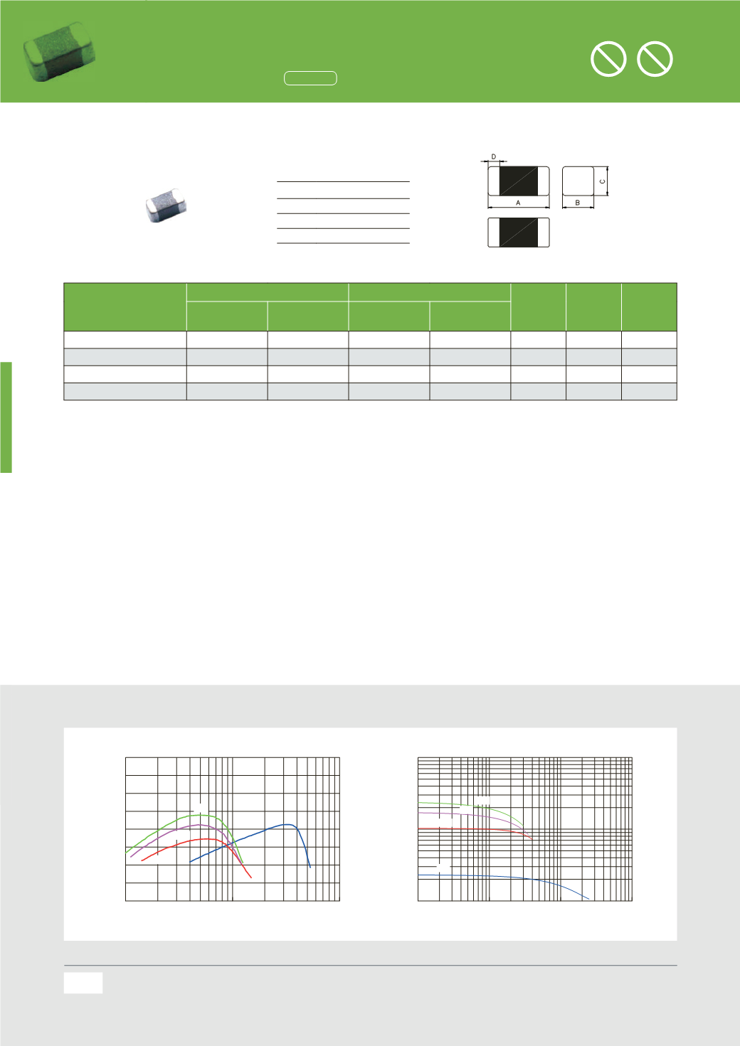
Q vs Frequency, DC Bias Characteristics (Typical)
1
10
100
FREQUENCY(MHz)
0
10
20
30
40
50
60
70
80
Q
FCI1005F-Series Q vs Freq.
R22
1
R0
1
R8
2
R2
1
10
100
1000
DCCURRENT(mA)
0.1
1
10
INDUCTANCE (uH)
FCI1005F-Series LVS IDC.
R22
1
R0
1
R8
2
R2
62
Q vs Frequency, DC Bias Characteristics (Typical)
Multilayer Ferrite Chip Inductors
(0402
inch)
Dimensions
Specifications
Chip Size
A
1.00
±0.10
B
0.50
±0.10
C
0.50
±0.10
D
0.25
±0.10
Units: mm
Part Number
Inductance(
uH
)
Q
Rated Current
(
mA) max.
DC
Resistance
(
Ω
)
max.
SRF
(
MHz) min.
Tolerance Test Frequency
(
Hz)
min.
Test Frequency
(
MHz)
FCI1005F-R22K 0.22
±
10% 60
mV / 25M 10
25
25
1.20
110
FCI1005F-1R0K 1.0
±
10% 60
mV / 10M 20
10
15
0.90
40
FCI1005F-1R8K 1.8
±
10% 60
mV / 10M 20
10
15
1.45
30
FCI1005F-2R2K 2.2
±
10% 60
mV / 10M 20
10
10
1.70
28
Q vs Frequency, D Bias Characteristics (Typical)
1
10
100
FREQUENCY(MHz)
0
10
20
30
40
50
60
70
80
Q
FCI1005F-Series Q vs Freq.
R22
1
R0
1
R8
2
R2
1
10
100
100
DC CURRENT(mA)
0.1
1
10
INDUCTANCE (uH)
FCI1005F-Series L VS IDC.
R22
1
R0
1
R8
2
R2
All the data listed in this catalogue are for reference only, TAI-TECH reserves the right
notification.
For the latest specification, please visit our website:
Multilayer Ferrite Chip Inductors
(0402
inch)
Dimensions
Specific tions
Chip
A
B
C
D
Units: mm
Part Number
Inductance(
uH
)
Q
Rated Current
(
mA) max.
Tolerance Test Frequency
(
Hz)
min.
Test Frequency
(
MHz)
FCI1005F-R22K 0.22
±
10% 60
mV / 25M 10
25
25
FCI1005F-1R0K 1.0
±
10% 60
mV / 10M 20
10
15
FCI1005F-1R8K 1.8
±
10% 60
mV / 10M 20
10
15
FCI1005F-2R2K 2.2
±
10% 60
mV / 10M 20
10
10
Q vs Frequency, DC Bias Characteristics (Typical)
1
10
1 0
FREQUENCY(MHz)
0
10
20
30
40
50
60
70
80
Q
FCI1005F-Series Q vs Freq.
R22
1
R0
1
R8
2
R2
1
10
DC CURREN
0.1
1
10
INDUCTANCE (uH)
FCI1005F-Series
R22
1
R0
1
R8
2
R2
62
62
All the data listed in this catalogue are for reference only, TAI-TECH reserves the right to alter or revise the speci cations without prior noti cation.
For the latest speci cation, please visit our website:
Remark


